
How Solar Racking Systems Are Tested to Support Ultra-Thin Glass-Glass PV Modules Safely
July 02, 2026
Ultra-thin glass-glass modules are becoming increasingly attractive for modern photovoltaic projects because they offer durability, improved bifacial performance potential, and long-term protection against environmental stress. However, their thinner glass design also creates new engineering challenges for mounting system compatibility.
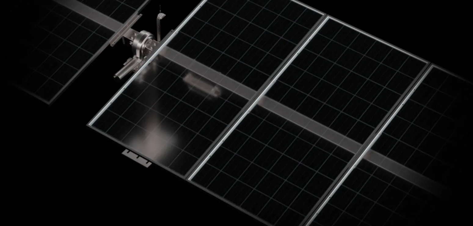
Ultra-thin glass-glass modules may require more precise mechanical support than conventional module designs, depending on their frame, glass thickness, and approved mounting configuration. The interaction between module stiffness, clamp positions, wind pressure, and structural deformation must be carefully evaluated before installation.
For this reason, experienced solar mounting structure manufacturers use a combination of engineering simulations, laboratory testing, and field validation to determine safe structural load limits. These processes help ensure that racking systems provide reliable support without creating excessive stress on delicate module components.
Understanding the Structural Challenges of Ultra-Thin Glass-Glass Modules
Glass-glass modules use glass layers on both sides of the photovoltaic laminate, replacing the traditional glass-backsheet configuration. While this structure improves environmental resistance, reducing glass thickness can affect mechanical behavior under external forces.
The main concern is not simply the total weight of the module. Engineers must understand how the module reacts when exposed to uneven pressure, vibration, thermal expansion, and dynamic wind loading.
A mounting structure that works well with standard modules may not automatically be suitable for ultra-thin glass-glass designs. Differences in frame design, support points, and allowable bending levels can influence the overall reliability of the PV system.
Solar mounting structure manufacturers evaluate these factors during the design stage to avoid problems such as glass breakage, cell microcracks, or long-term performance losses.
Finite Element Analysis Before Physical Testing
Before building prototypes, engineers typically use computer-based simulation to predict how the module and racking system behave under different loading scenarios.
Finite Element Analysis (FEA) allows designers to examine stress distribution across mounting rails, clamps, fasteners, and module surfaces. The simulation identifies areas where excessive pressure or deformation may occur.
For ultra-thin glass-glass modules, the analysis focuses on several critical points:
Clamp pressure and contact areas
Rail spacing and support locations
Wind uplift forces
Snow loading conditions
Structural deflection limits
This approach helps engineers optimize the mounting structure before physical validation. Adjustments to rail geometry, material thickness, and connection methods can be made earlier, reducing development risks.
Mechanical Load Testing Under Real Conditions
Simulation results must be verified through physical testing. Mechanical load tests reproduce environmental forces that solar projects may experience during operation.
International PV qualification procedures include mechanical load evaluation to confirm module durability under pressure conditions. These tests examine whether modules maintain electrical performance and structural integrity after exposure to repeated forces.
For ultra-thin glass-glass modules, testing often includes:
Static load testing
Dynamic load testing
Wind pressure simulation
Clamp compatibility assessment
Long-duration stress evaluation
The goal is not only to confirm whether a module survives a single load event but also to understand how the complete module-racking combination performs over time.
Evaluating Clamp Design and Contact Pressure
One of the most important validation steps involves the connection between the module and the mounting system.
Ultra-thin glass-glass modules can be more sensitive to concentrated forces. Poorly designed clamps may create localized stress points that increase the risk of damage.
Engineers evaluate:
Clamp width
Contact surface design
Fastener torque requirements
Material compatibility
Installation tolerance
A properly engineered clamping system distributes pressure evenly across the module edge area. This reduces mechanical stress while maintaining sufficient holding strength during severe weather conditions.
The design process must balance two requirements: strong attachment during high winds and gentle support for fragile module structures.
Wind and Snow Load Verification for Project Conditions
Structural load limits cannot be separated from actual project environments. A mounting system designed for one location may not perform identically in another due to different climate conditions.
During validation, engineers consider site-specific factors such as:
Maximum wind speed
Wind direction and turbulence
Snow accumulation
Installation height
Tilt angle
Terrain conditions
Solar mounting structure manufacturers use these parameters to determine whether the racking design can safely support ultra-thin modules in different applications.
For large-scale solar farms, this step is especially important because small structural weaknesses can affect thousands of modules across the entire installation.
Field Validation and Installation Feedback
Laboratory testing provides controlled results, but real-world installation experience also contributes valuable information.
Field validation helps engineers understand practical challenges, including transportation handling, installation accuracy, and long-term exposure conditions.
Feedback from EPC contractors and installers can reveal issues that may not appear during laboratory testing. For example, installation speed, clamp adjustment methods, and construction tolerances can influence the final structural performance.
Combining field experience with engineering data allows manufacturers to continuously improve mounting solutions for new module technologies.
Selecting the Right Mounting Partner for Ultra-Thin Modules
When choosing a racking supplier for ultra-thin glass-glass modules, project owners should look beyond standard load ratings.
Important evaluation factors include:
Experience with advanced module technologies
Engineering calculation capability
Testing procedures and documentation
Adaptability for different module dimensions
Understanding of local environmental requirements
A reliable supplier should be able to explain how structural limits were determined rather than only providing general product specifications.
Proper validation reduces installation risks, improves project reliability, and helps protect the long-term energy output of the solar system.
Conclusion
Ultra-thin glass-glass modules require a higher level of structural engineering compared with traditional PV modules. Load validation involves simulation, mechanical testing, connection optimization, and real-world verification to ensure safe and durable performance.
Developing mounting solutions for next-generation solar technologies requires a combination of engineering knowledge and real-world project experience, in our opinion. More sophisticated photovoltaic systems with dependable structural performance are on the horizon, and Antaisolar is there to help with constant innovation and thorough testing.
Ultra-thin glass-glass modules may require more precise mechanical support than conventional module designs, depending on their frame, glass thickness, and approved mounting configuration. The interaction between module stiffness, clamp positions, wind pressure, and structural deformation must be carefully evaluated before installation.
For this reason, experienced solar mounting structure manufacturers use a combination of engineering simulations, laboratory testing, and field validation to determine safe structural load limits. These processes help ensure that racking systems provide reliable support without creating excessive stress on delicate module components.
Understanding the Structural Challenges of Ultra-Thin Glass-Glass Modules
Glass-glass modules use glass layers on both sides of the photovoltaic laminate, replacing the traditional glass-backsheet configuration. While this structure improves environmental resistance, reducing glass thickness can affect mechanical behavior under external forces.
The main concern is not simply the total weight of the module. Engineers must understand how the module reacts when exposed to uneven pressure, vibration, thermal expansion, and dynamic wind loading.
A mounting structure that works well with standard modules may not automatically be suitable for ultra-thin glass-glass designs. Differences in frame design, support points, and allowable bending levels can influence the overall reliability of the PV system.
Solar mounting structure manufacturers evaluate these factors during the design stage to avoid problems such as glass breakage, cell microcracks, or long-term performance losses.
Finite Element Analysis Before Physical Testing
Before building prototypes, engineers typically use computer-based simulation to predict how the module and racking system behave under different loading scenarios.
Finite Element Analysis (FEA) allows designers to examine stress distribution across mounting rails, clamps, fasteners, and module surfaces. The simulation identifies areas where excessive pressure or deformation may occur.
For ultra-thin glass-glass modules, the analysis focuses on several critical points:
Clamp pressure and contact areas
Rail spacing and support locations
Wind uplift forces
Snow loading conditions
Structural deflection limits
This approach helps engineers optimize the mounting structure before physical validation. Adjustments to rail geometry, material thickness, and connection methods can be made earlier, reducing development risks.
Mechanical Load Testing Under Real Conditions
Simulation results must be verified through physical testing. Mechanical load tests reproduce environmental forces that solar projects may experience during operation.
International PV qualification procedures include mechanical load evaluation to confirm module durability under pressure conditions. These tests examine whether modules maintain electrical performance and structural integrity after exposure to repeated forces.
For ultra-thin glass-glass modules, testing often includes:
Static load testing
Dynamic load testing
Wind pressure simulation
Clamp compatibility assessment
Long-duration stress evaluation
The goal is not only to confirm whether a module survives a single load event but also to understand how the complete module-racking combination performs over time.
Evaluating Clamp Design and Contact Pressure
One of the most important validation steps involves the connection between the module and the mounting system.
Ultra-thin glass-glass modules can be more sensitive to concentrated forces. Poorly designed clamps may create localized stress points that increase the risk of damage.
Engineers evaluate:
Clamp width
Contact surface design
Fastener torque requirements
Material compatibility
Installation tolerance
A properly engineered clamping system distributes pressure evenly across the module edge area. This reduces mechanical stress while maintaining sufficient holding strength during severe weather conditions.
The design process must balance two requirements: strong attachment during high winds and gentle support for fragile module structures.
Wind and Snow Load Verification for Project Conditions
Structural load limits cannot be separated from actual project environments. A mounting system designed for one location may not perform identically in another due to different climate conditions.
During validation, engineers consider site-specific factors such as:
Maximum wind speed
Wind direction and turbulence
Snow accumulation
Installation height
Tilt angle
Terrain conditions
Solar mounting structure manufacturers use these parameters to determine whether the racking design can safely support ultra-thin modules in different applications.
For large-scale solar farms, this step is especially important because small structural weaknesses can affect thousands of modules across the entire installation.
Field Validation and Installation Feedback
Laboratory testing provides controlled results, but real-world installation experience also contributes valuable information.
Field validation helps engineers understand practical challenges, including transportation handling, installation accuracy, and long-term exposure conditions.
Feedback from EPC contractors and installers can reveal issues that may not appear during laboratory testing. For example, installation speed, clamp adjustment methods, and construction tolerances can influence the final structural performance.
Combining field experience with engineering data allows manufacturers to continuously improve mounting solutions for new module technologies.
Selecting the Right Mounting Partner for Ultra-Thin Modules
When choosing a racking supplier for ultra-thin glass-glass modules, project owners should look beyond standard load ratings.
Important evaluation factors include:
Experience with advanced module technologies
Engineering calculation capability
Testing procedures and documentation
Adaptability for different module dimensions
Understanding of local environmental requirements
A reliable supplier should be able to explain how structural limits were determined rather than only providing general product specifications.
Proper validation reduces installation risks, improves project reliability, and helps protect the long-term energy output of the solar system.
Conclusion
Ultra-thin glass-glass modules require a higher level of structural engineering compared with traditional PV modules. Load validation involves simulation, mechanical testing, connection optimization, and real-world verification to ensure safe and durable performance.
Developing mounting solutions for next-generation solar technologies requires a combination of engineering knowledge and real-world project experience, in our opinion. More sophisticated photovoltaic systems with dependable structural performance are on the horizon, and Antaisolar is there to help with constant innovation and thorough testing.
end